Site Directory
Projects List
Click for alphabetical list of the projects.
Gauss Meter
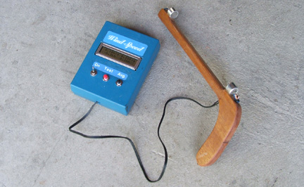
Wind Meter
Infrared Tachometer
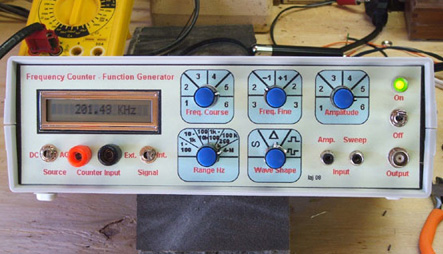
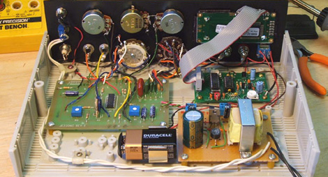
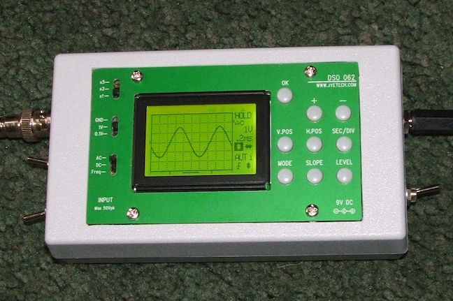
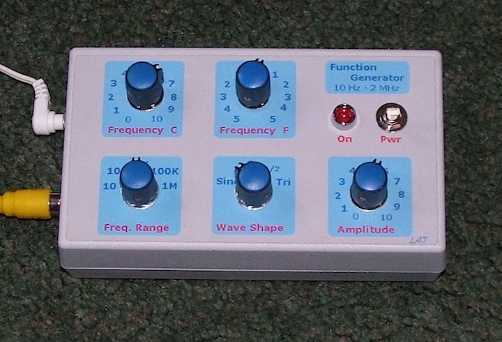
Function Generator/Frequency Counter
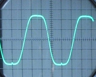
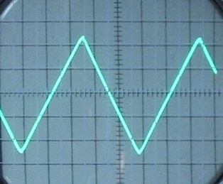
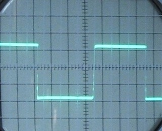
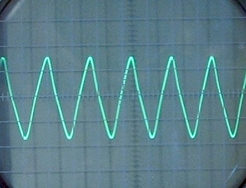
(Oscilloscope Traces)
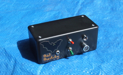
Audio Visual Bat Detector
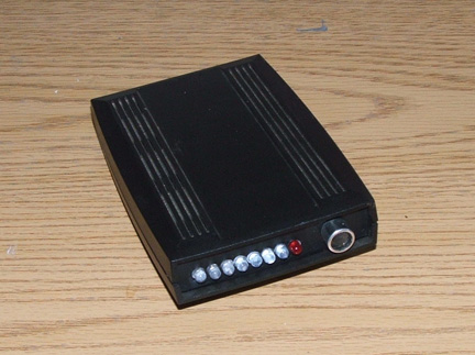
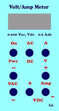
Digital Volt/Amp Meter
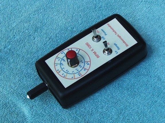
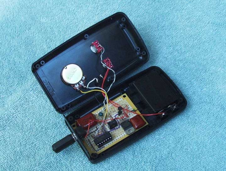
Stroboscopic Tachometer
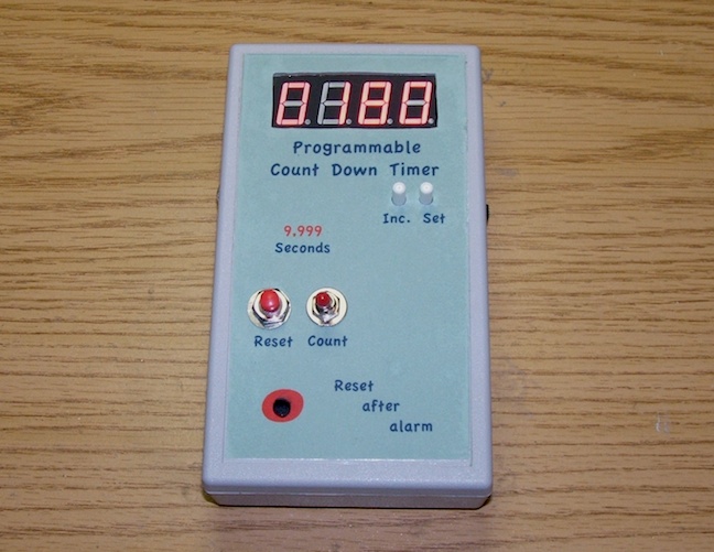
Programmable Counter
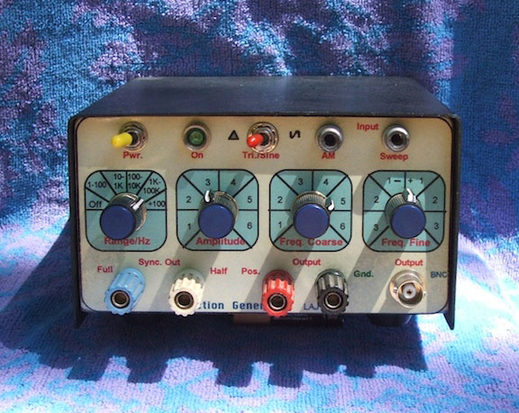
Function Generator
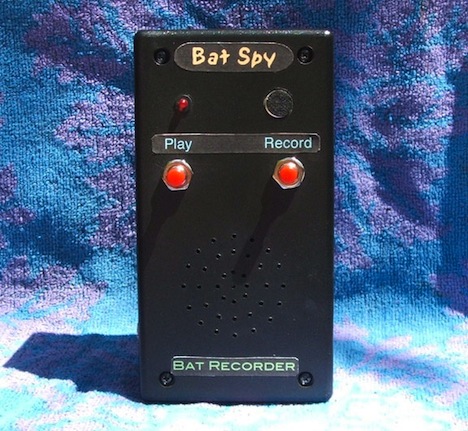
Bat Spy (Recorder)
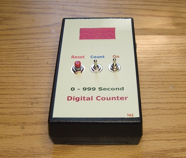
Three Digit Counter
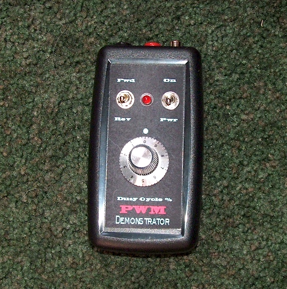
Pulse Width Modulator
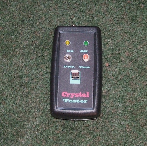
Crystal Tester (Transistor)
Ultra/Audio Tone Generator
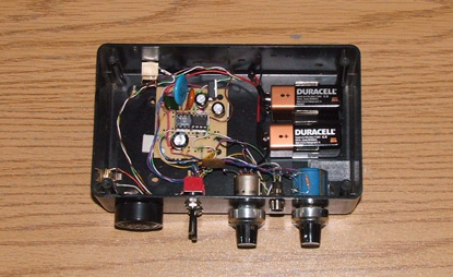
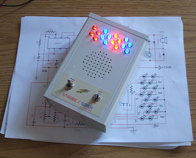
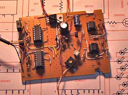
Strobe Light/Siren
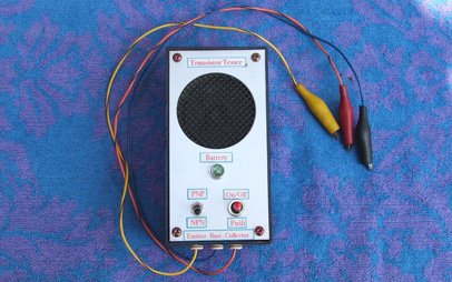
Transistor Tester
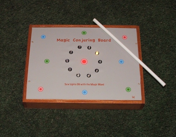
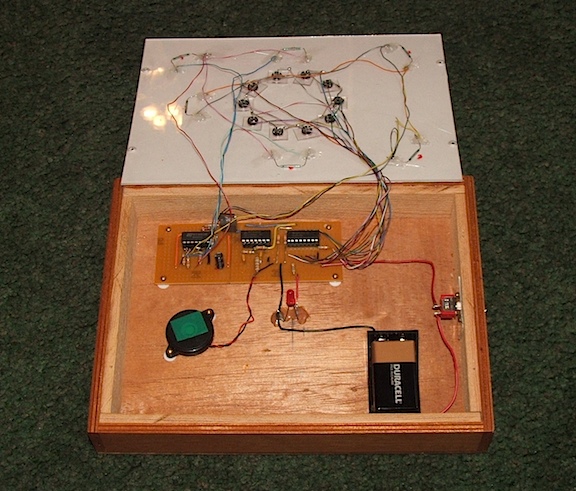
Magic Conjuring Board and Magic Wand
Bat Call Simulator
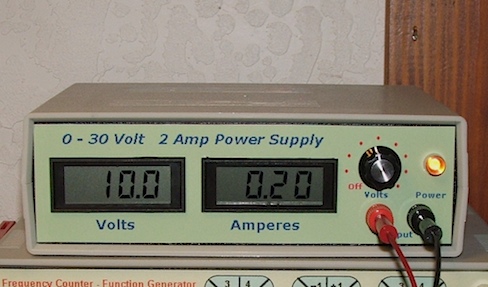
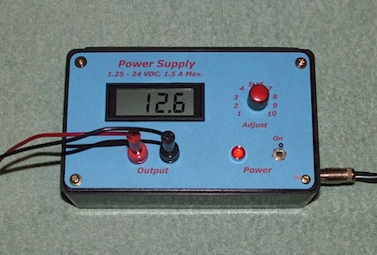
1.25-30 VDC 3 Amp Power Supply
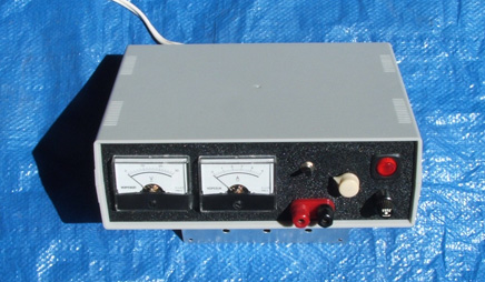
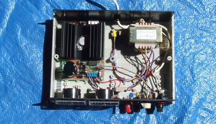
2 Amp Power Supply
1.5 Amp Power Supply
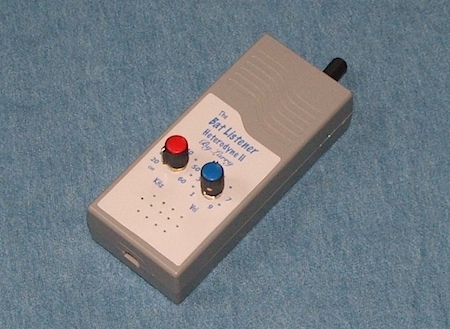
The Bat Listener
Lux Meter
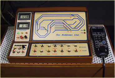
Model Train Throttle
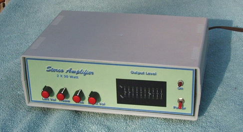
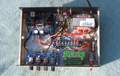
30 Watt Stereo Amplifier
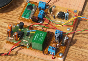
Infrared Detector for a Model Train
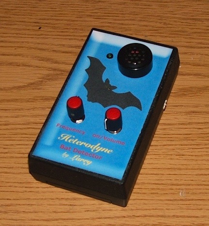
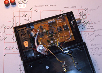
Heterodyne Bat Detector
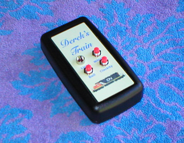
Derek's Train Sounds
NE555 AF/RF Generator
FM Transmitter & Receiver
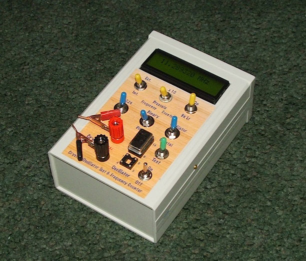
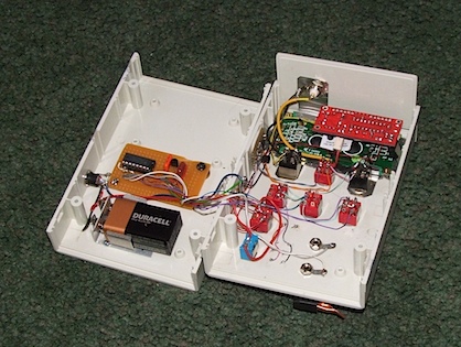
Crystal/Oscillator Tester and
Frequency Counter
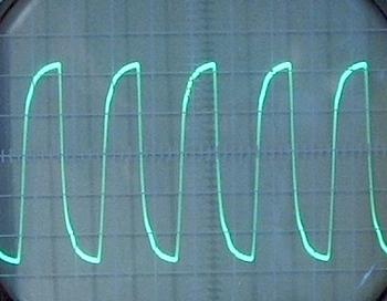
(Oscilloscope traces of crystal & oscillator)
LC Meter
Zener Diode Tester
Digital Oscilloscope
Programmable Counter
Function Generator II
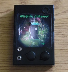
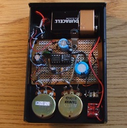
Wildlife Listener
3 Watt Audio Amplifier
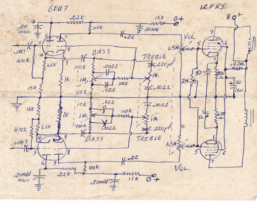
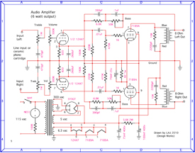
Tube Amplifier Circuits
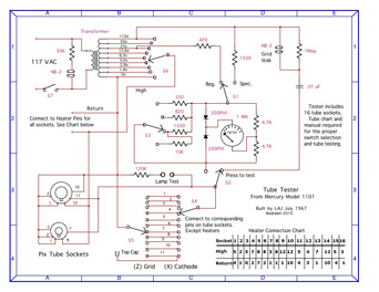
Tube Tester Schematic
Capacitance Converter
Here is an alphabetical list of the projects.
 = back to Projects List
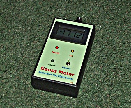
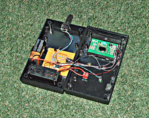
Gauss Meter
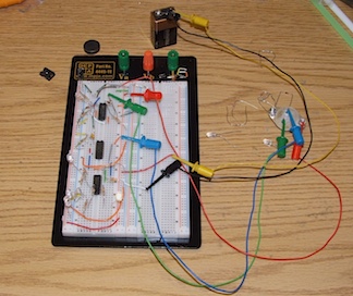
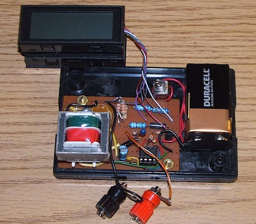
After some tedious work on the breadboard I finally got my Gauss meter to work just right. It measures from 1 to 1,999 gauss. A red LED indicates the north pole of the magnet being measured and a green LED shows the south pole. (See the schematic for details.) The gauss meter is built around the A1302 Linear Radiometric Hall Effect Sensor with a LM358 Op Amp to drive the LEDs and a 200mA digital panel meter for the readout. The meter reads minus (millivolts/gauss) for north pole and plus for south pole.
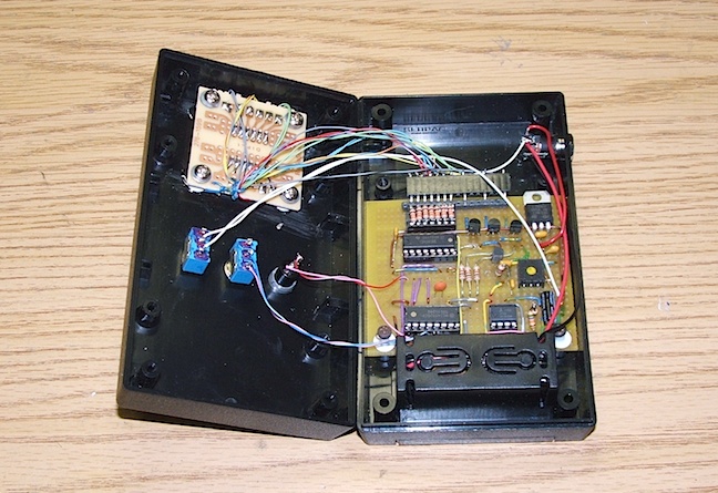
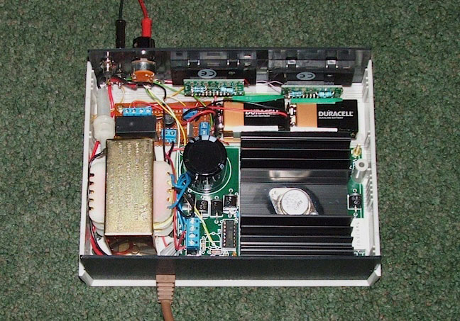
Glick here for the inside view.
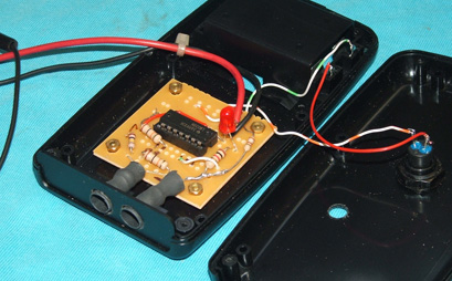
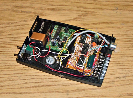
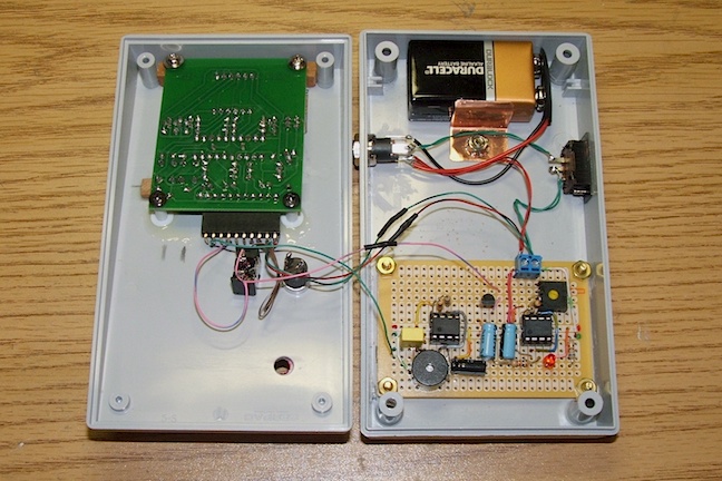
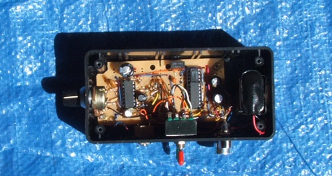

