Site Directory
Projects List - Page Two
Click for alphabetical list of all the projects.
Audio Visual Bat Detector
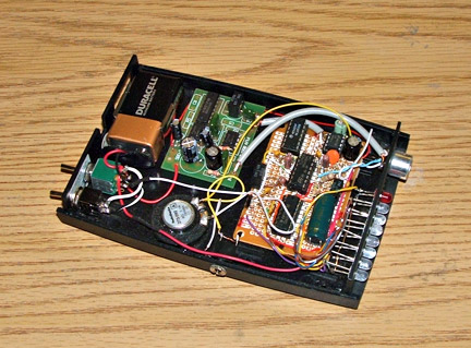
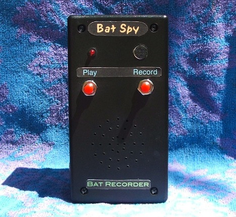
Bat Spy (Recorder)
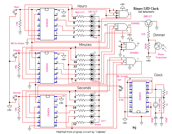
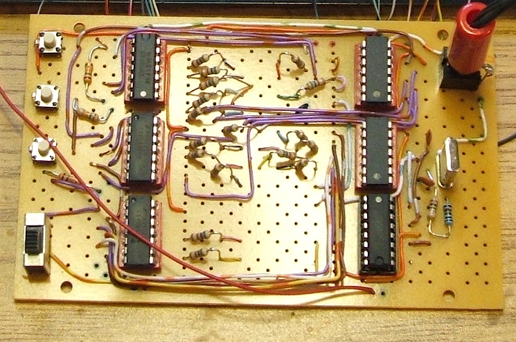
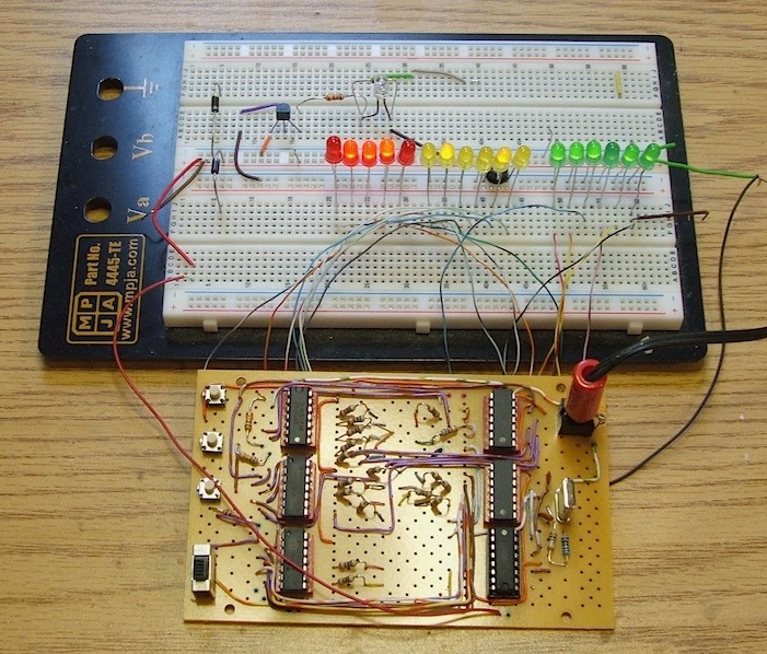
Binary Clock
LED Binary Clock
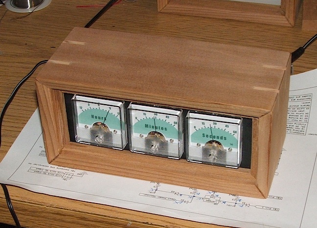
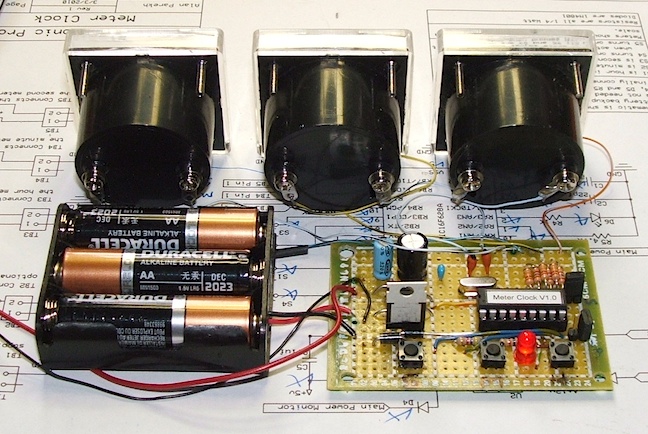
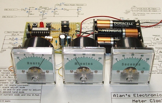
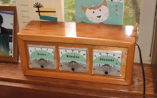
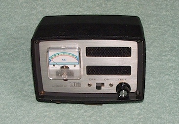
Panel Meter Clock
Three Digit Counter
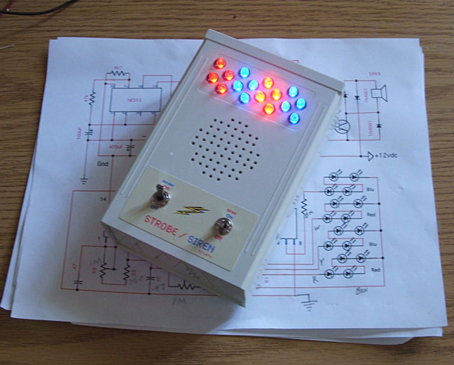
Strobe Light/Siren
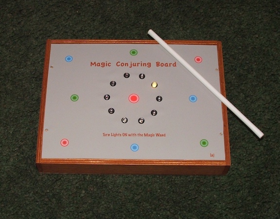
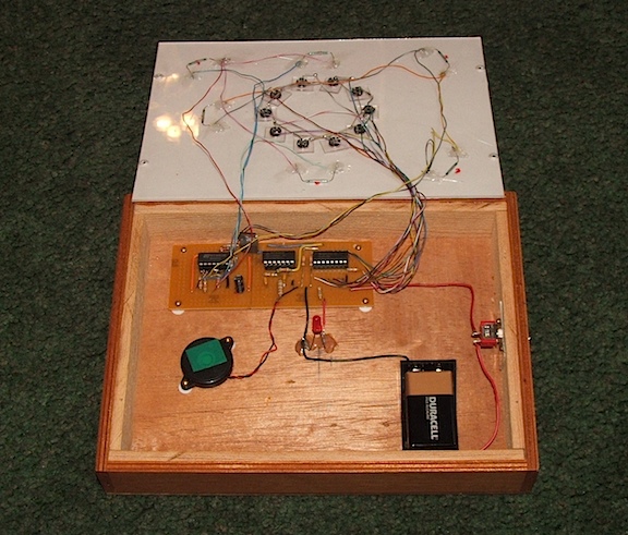
Magic Conjuring Board and Magic Wand
Bat Call Simulator
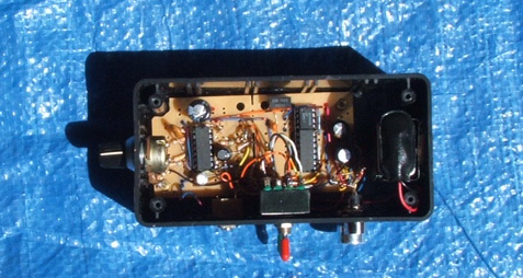
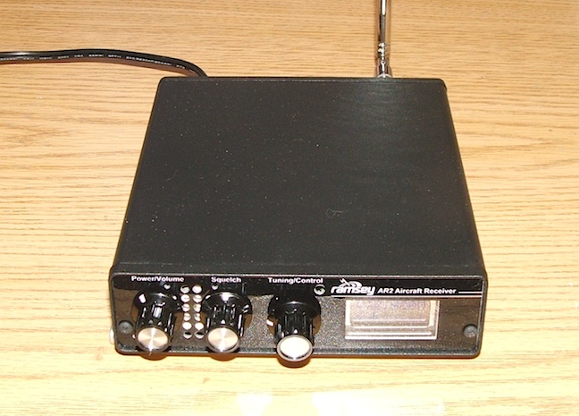
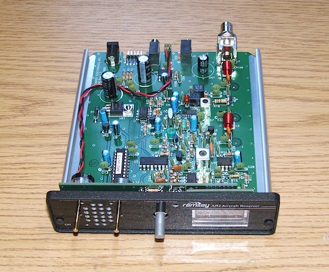
Aircraft Band Receiver
The Bat Listener
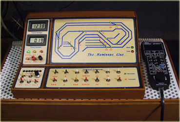
Model Train Throttle
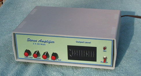
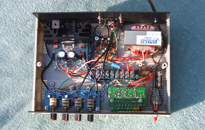
30 Watt Stereo Amplifier
Infrared Detector for a Model Train
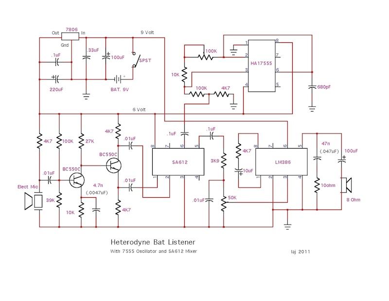
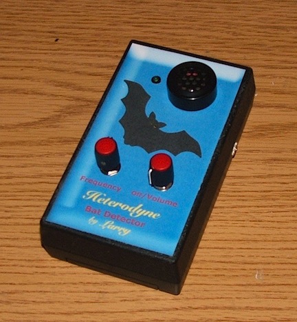
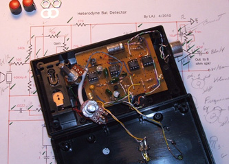
Heterodyne Bat Detector
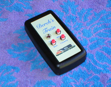
Derek's Train Sounds
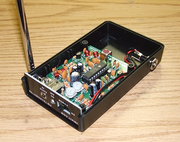
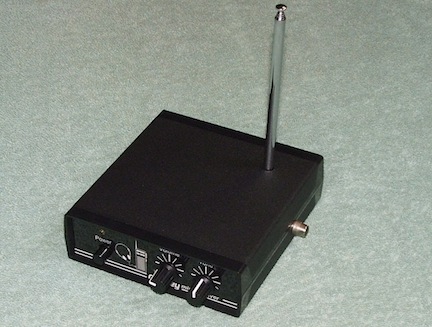
FM Transmitter & Receiver
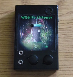
Wildlife Listener
3 Watt Audio Amplifier
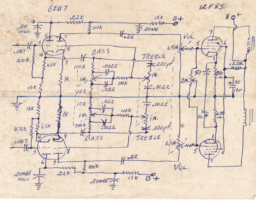
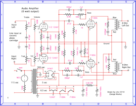
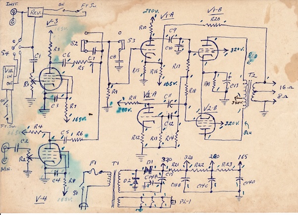
Tube Amplifier Circuits
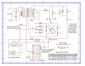
Tube Tester Schematic
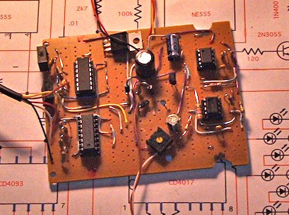
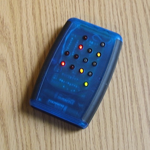
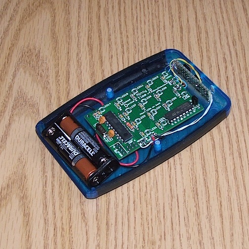
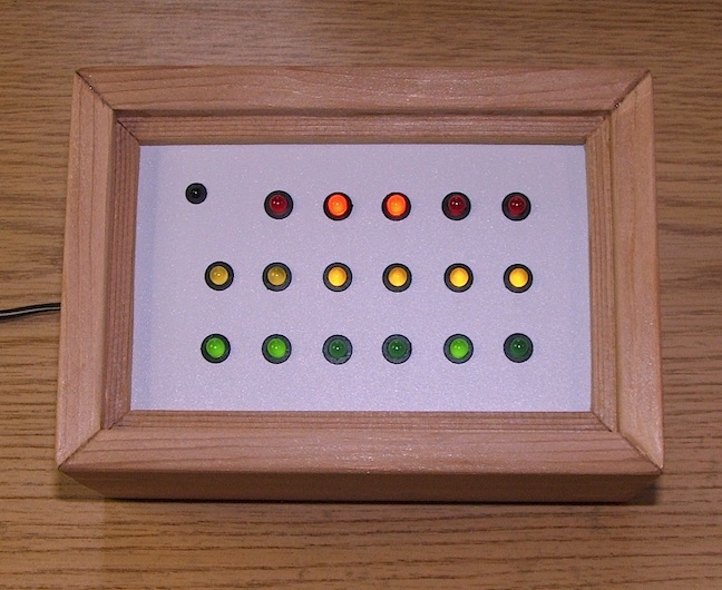
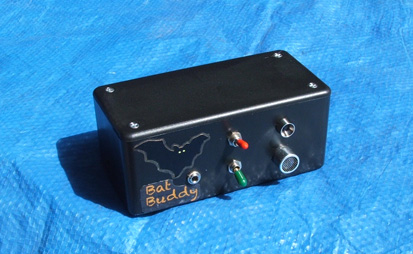
A/V Bat Detector
My audio/visual bat detector. With this gadget you can hear the bat call and see the flashing LEDs at the same time. When a bat call comes in, the LEDs will light relative to the frequency received. One LED = 20KHz, eight LEDs = 80KHz.